To guarantee the correct functioning of the Cantilever Gate System, please follow the instructions as outlined in this document provided by the manufacturer. It is important to have the correct length of the counterbalance and the spacing between the carriages. The size of the foundation is also critical. Please call us or email us for further questions or help with configuring your gate.
IMPORTANT NOTE:
The hardware will provide sliding and cantilever action, however, the gate itself must be self supporting and adequately braced to prevent sagging.
![]()
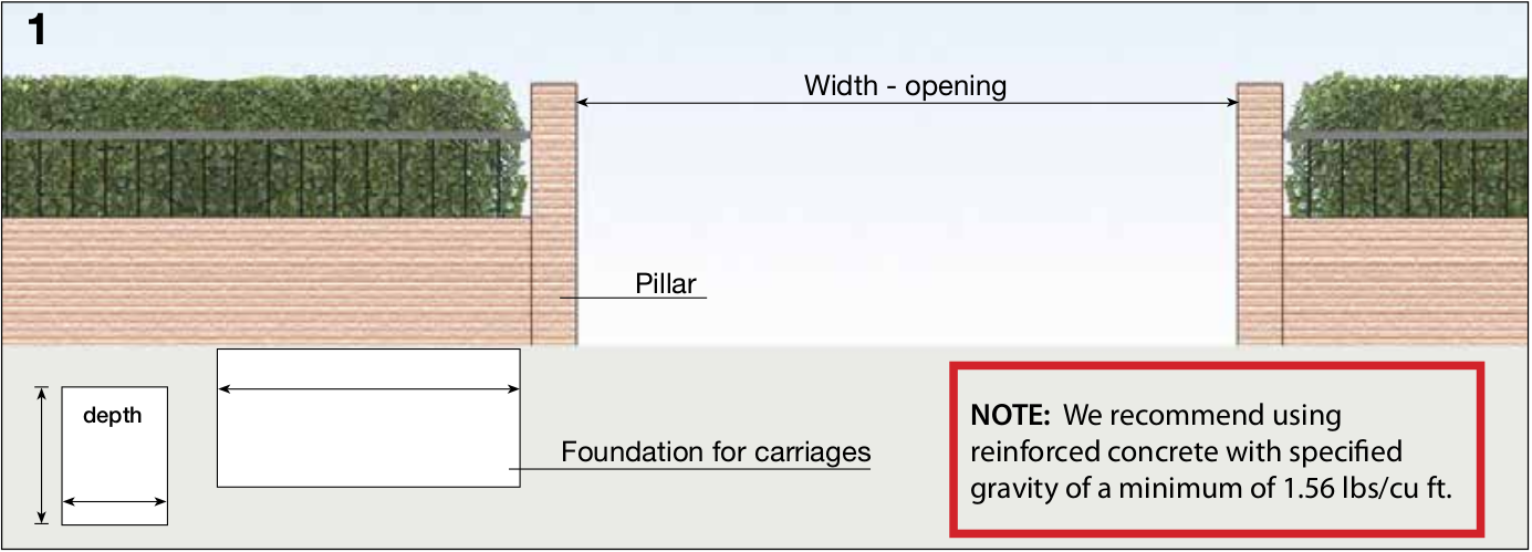
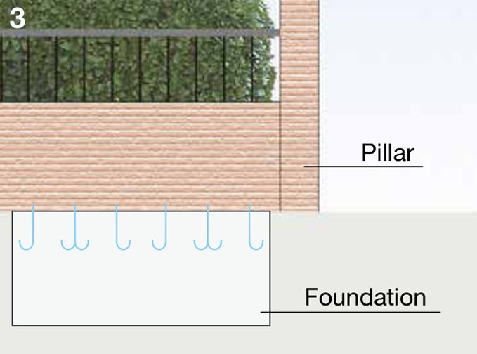
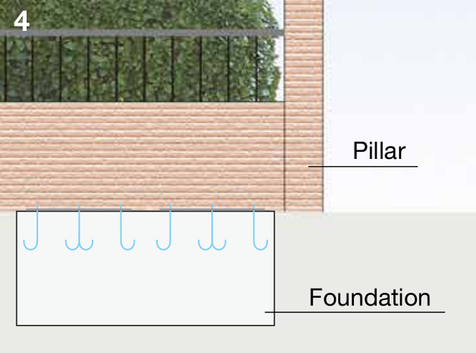
1 - Preparation of the foundation where the carriage set will be installed.
Prepare the foundation site and pour as per the measurements received in your configuration sheet. If you feel the depth of the concrete pad should be deeper due to the frost line please add sufficient concrete to accommodate this.
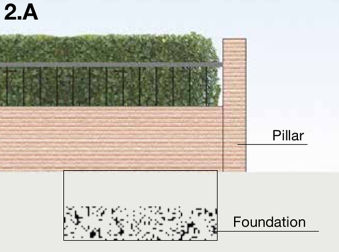
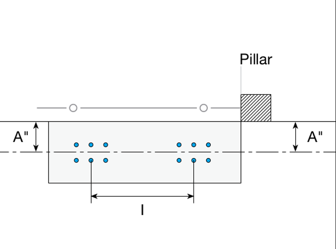
2.A - Positioning of the tie rods.
Once the foundation is laid, fill the hole with cement until the excavation area is covered.
Sink the tie rods in the concrete so they will be equally centered on the slab and tail end of the gate.
Be sure the center-to-center distance on the carriages is as specified on your configuration sheet (letter “I”) See next page for positioning diagram 2.B.
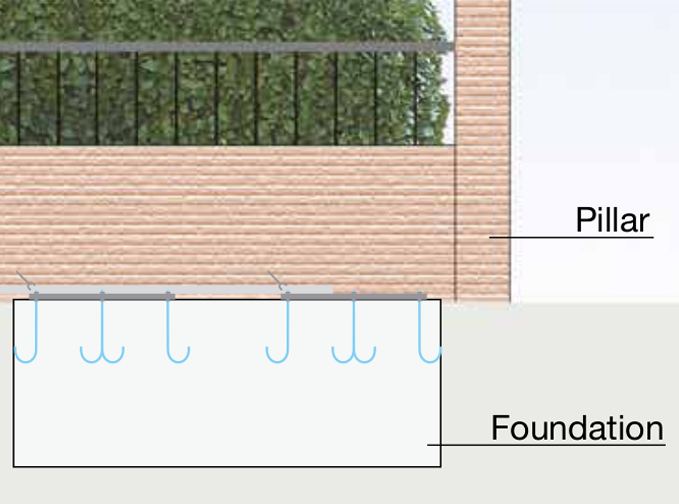
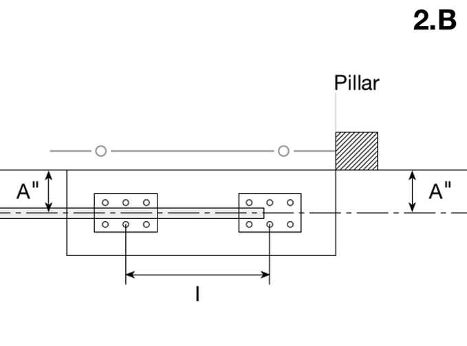
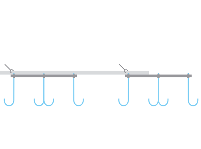
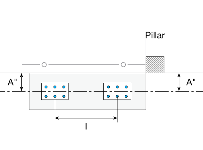
2.B – Positioning of the tie rods.
Once the foundation is laid, fill the hole with cement until the excavation area is covered.
Sink the tie rods in the concrete so they will be equally centered on the slab and tail end of the gate.
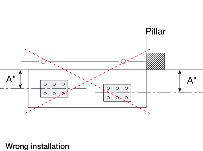
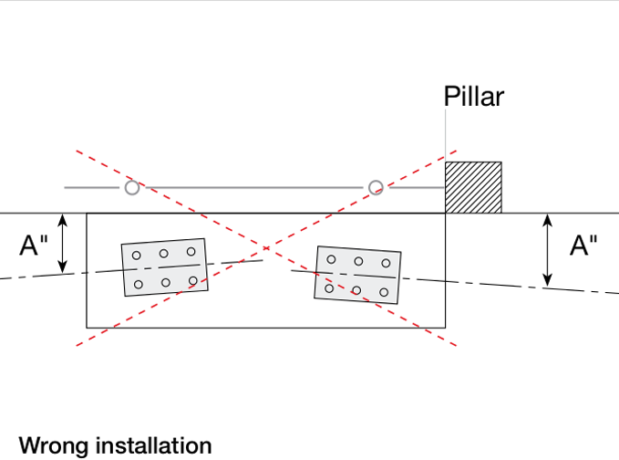
Be sure the center-to-center distance on the carriages is as specified on your configuration sheet (letter “I”).
A template can be made to assist with positioning.
Note: The top of the bolt/tie rod should stick out of the cement at least 2″. Keep nut on top of concrete, do not sink in.
3 - Wait until the foundation is set [about 24 hours].
Once verified that the foundation is well hardened, loosen the nuts off the tie rods, clean the area where the counter plates
will rest and prepare for the assembly of the carriages.
4 - Position the counter plate [not available for the “mini” models].
Once the surface area has been cleaned, re-fasten the nut so it rests on the concrete and place the counter plates on the
tie rods. The holes on the counter plates should easily fit over the tie rods and have some room for adjustment.
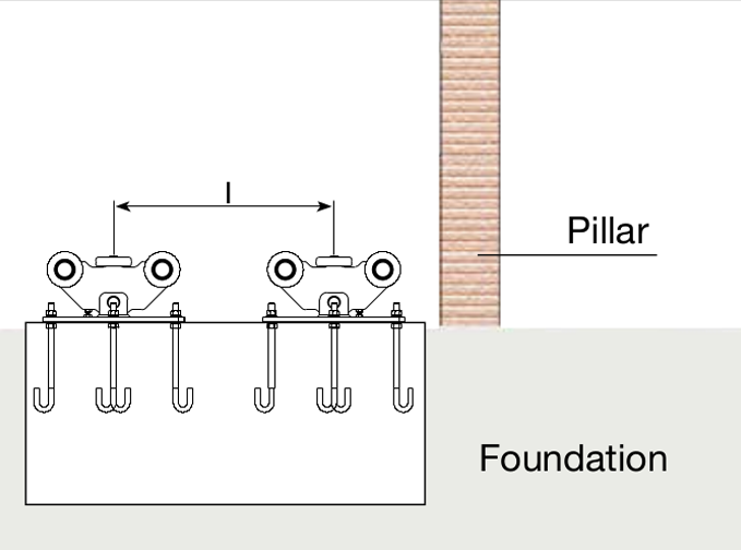
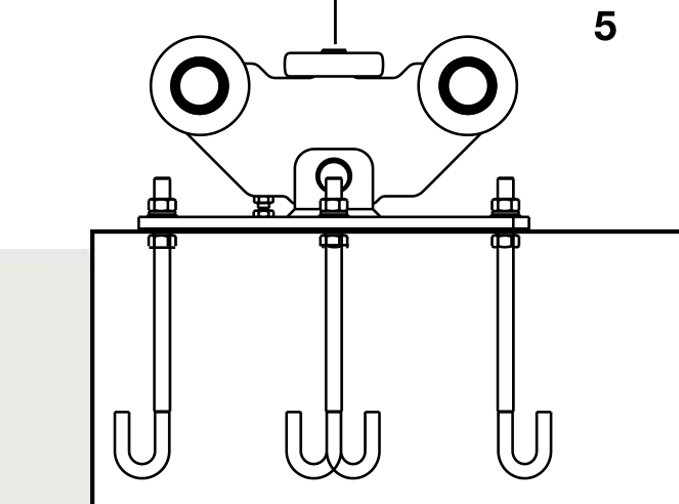
5 - Position the carriages on top of the counter plates, if they were used.
The carriages are now ready to be placed either on top of the counter plate or on the concrete. Ensure the elastic washer is
put down on the carriage first and then the nut. The nuts can now be tightened. While tightening the nuts, constantly check
that the carriages are level. If carriages are not level, then adjust the bolts under the carriage plate/carriage itself until the
carriages are level.
Note: When mounting the CGA carriages, make sure the regulating screws are facing towards the outside as showing in picture below.
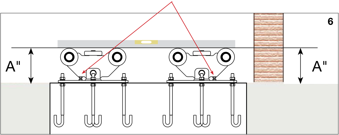
6 - Verify that the carriages are level.
Carriages shown are the CGA-350P.
The CGS models do not have the center bolt.
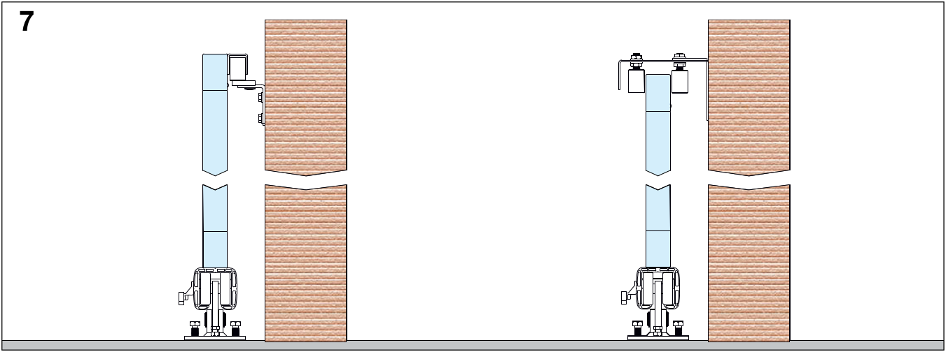
7- Fasten the top guide plate.
Now that the gate has been placed on the carriages, it is time to fasten a top guide plate to ensure stability of the gate itself.
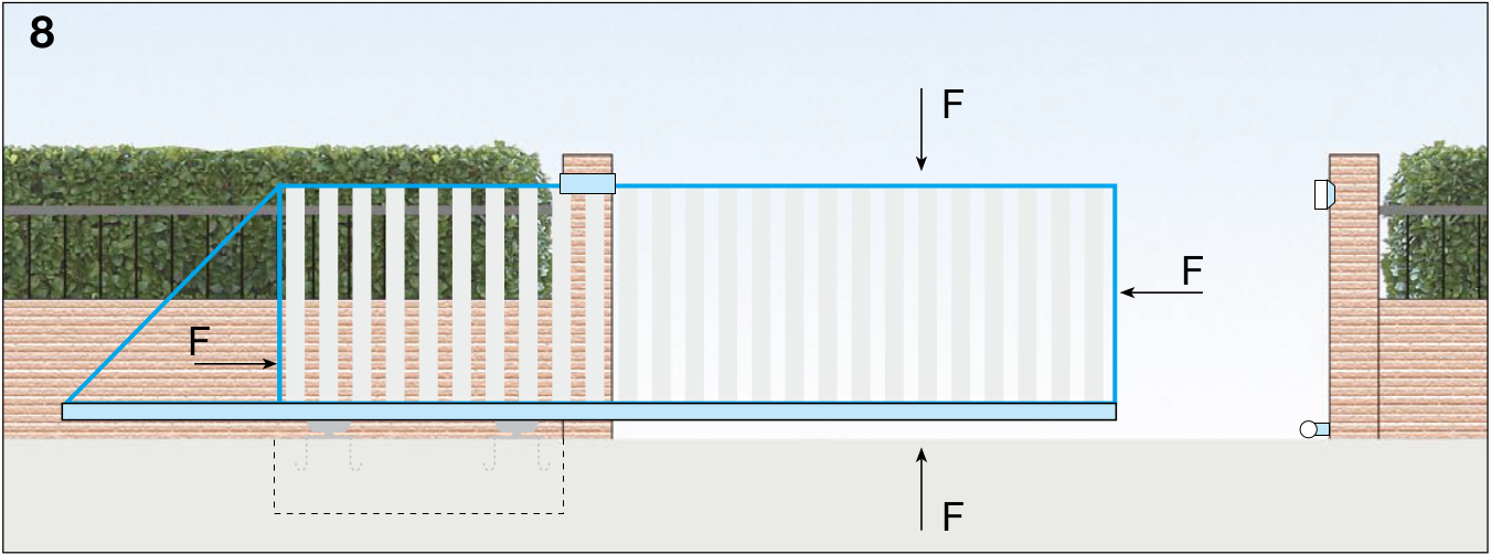
8 - Manually test the gates functionality.
Once the gate accessories have been added, check the gates performance and make any necessary adjustments.
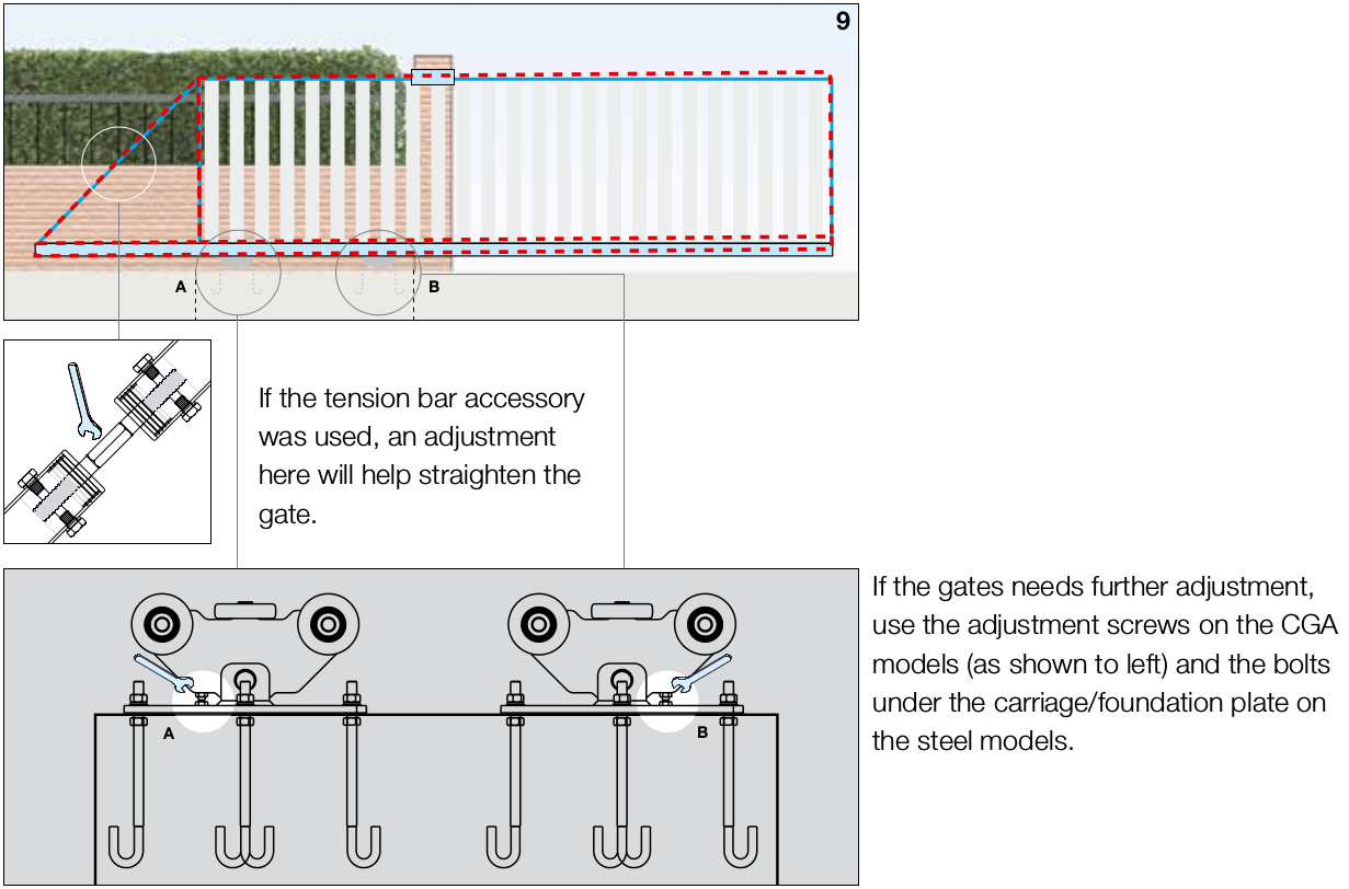
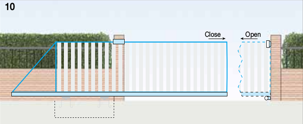
10 - Run the gate manually until it rests completely against the lower end cup situated on the pillar.