
DuraGates — Cantilever Gates, Evolved
Optimizing Cantilever Configurations
It is important to understand what the configurator does when you run a configuration, so you can understand how to “manipulate” it to get the results you want. The Comunello configurator always returns a minimum length configuration for the carriage selected, based on your gate’s opening length and weight. The answer to getting a different result is simple, but not intuitive: you pad the weight to get either the total gate length or carriage spacing you want.
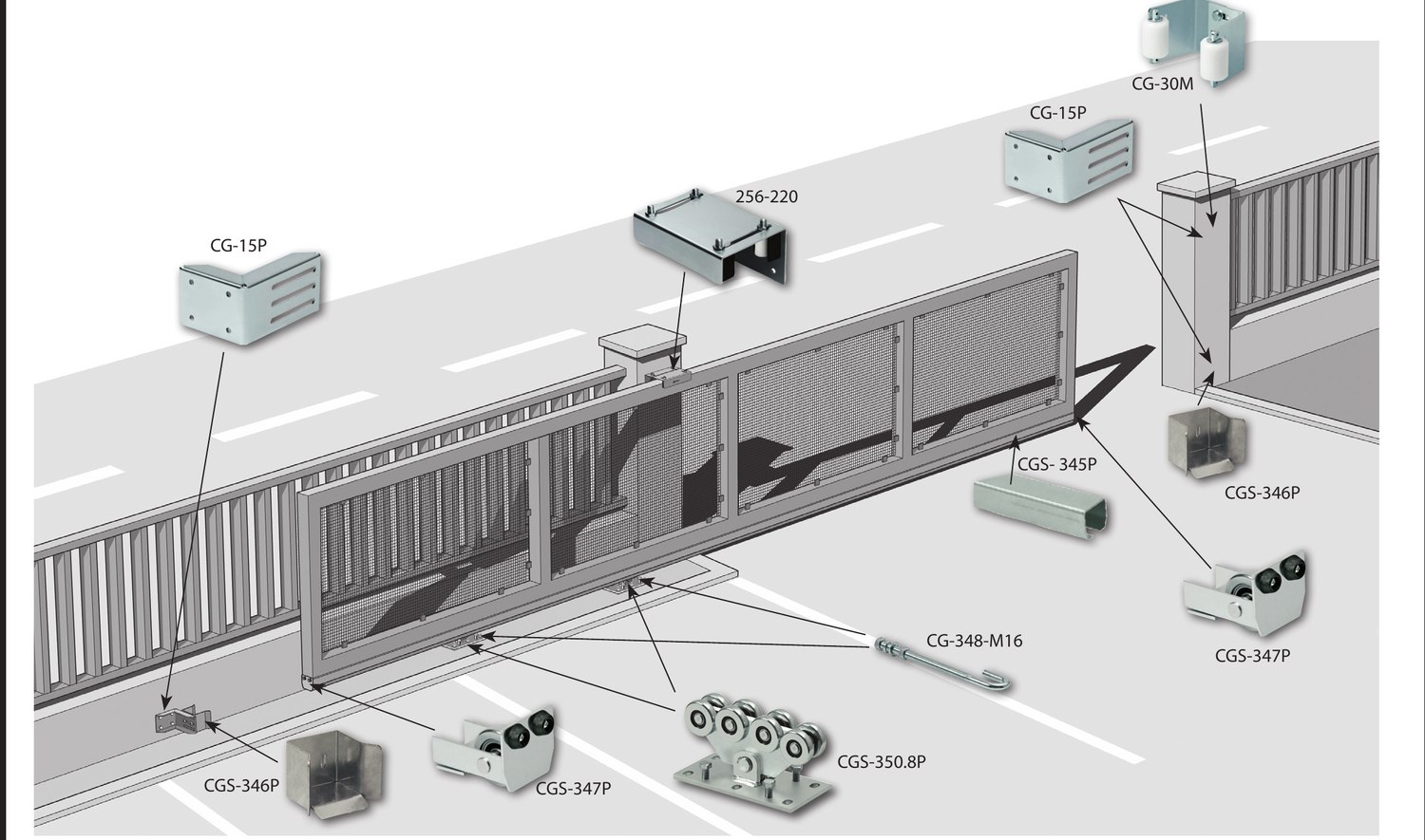
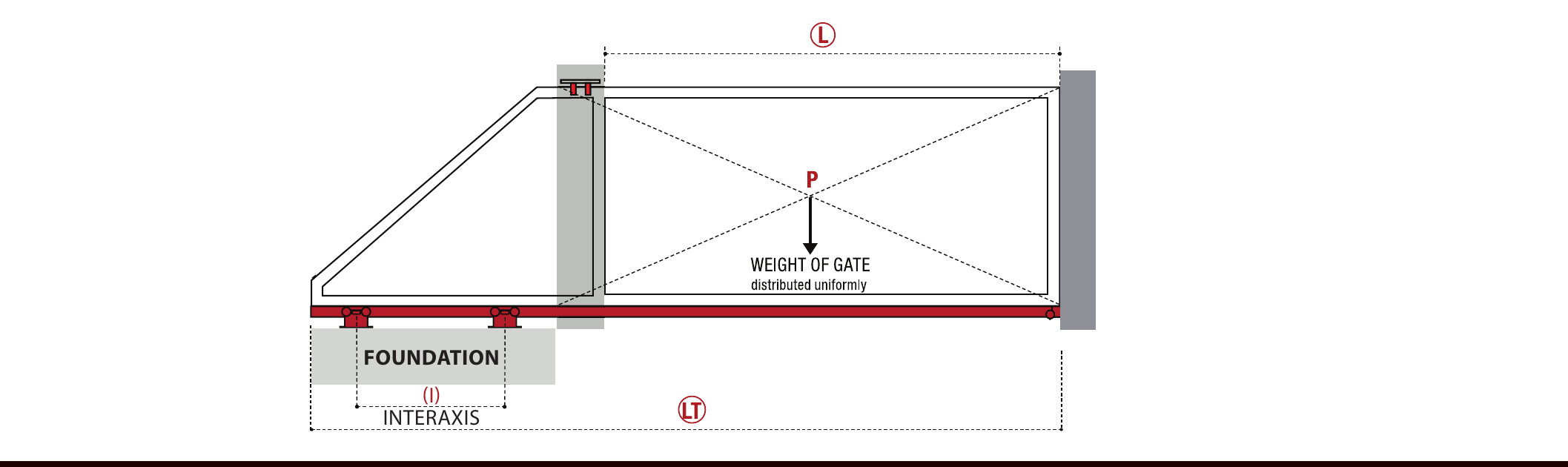
Key Terms
Every table in this guide refers back to these four variables.
To Configure a Gate, You Have Three Inputs
- Gate frame or hardware material: Steel, Aluminum, or Stainless Steel.
- Gate opening length, in fractional ft (Ex: 20 ft 6 inches = 20.5 ft).
- Weight of the cantilevered portion of the gate, in pounds.
What Is an Ideal Configuration?
When you run a configuration, it ALWAYS returns a minimum length configuration for the weight and opening input. The tool available to manipulate, or optimize, the configuration is the weight. For a given opening size, increasing the weight will give a longer gate, an increased carriage spacing, and a configuration with higher capacity.
We define an ideal configuration as one with a carriage spacing about 30% of the opening length. So, for a 20 ft (6m) opening, the ideal configuration would have a 6 ft (1.8m) carriage spacing. An ideal configuration gives you a gate operating on a foundation that is wide enough to eliminate the visible “teeter-totter” effect as the gate cycles, and sturdy enough to reduce or eliminate mis-alignment issues that cause gates to get harder to open over time.
It is always OK to add extra weight to the configuration because this increases the capacity of the system. It is never OK to decrease the weight below the actual weight of the gate, because this decreases the capacity and will lead to premature carriage or gate failure.
Optimizing the Configuration
Always begin with the actual opening size and weight of the gate cantilevered over the opening. Enter these specifications and proceed to the carriage selection page. Referring to the configuration instructions, choose a carriage that is available in the US. When you select a carriage, the page shows you the carriage spacing and total gate length.
If you proceed beyond the Carriage Selection Page, you cannot go back to the measurements page. Do not move forward until you have optimized the configuration for the carriage you have chosen.
Comunello has a range of 13 different steel carriages, so usually more than one of them will be close to the optimum size and capacity — you need to know which carriages are available through your supply chain and select accordingly. For example, for a Steel gate, 20 ft open, weighing 800 lbs, the configurator returns the following results for three carriages:
| Model | Configured Weight | Opening (L) | Total Length (LT) | Tail | Tail % | WT/FT | Interaxis (i) | i% |
|---|---|---|---|---|---|---|---|---|
| CGS-250.8M | 800 lbs | 20’0″ (240″) | 29’10″ (358″) | 9’10″ | 49% | 40.0 | 8’1″ | 40% |
| CGS-250.8P | 800 lbs | 20’0″ (240″) | 26’8″ (320″) | 6’8″ | 33% | 40.0 | 4’5″ | 22% |
| CGS-350.8P | 800 lbs | 20’0″ (240″) | 25’5″ (305″) | 5’5″ | 27% | 40.0 | 3’1″ | 15% |
The 250.8M will have a carriage spacing of 40% of the opening and the 250.8P has a 22% spacing. Either will work, and neither is “optimal.” For an optimal configuration, picking the 250.8P carriage and padding the weight to 990 lbs gives a 28 ft gate with a 40% tail section (2 ft shorter than top track hardware) and a spacing of 29%. This configuration gives a gate with 20% more capacity than needed and will extend the service life of the gate.
| Model | Configured Weight | Opening (L) | Total Length (LT) | Tail | Tail % | WT/FT | Interaxis (i) | i% |
|---|---|---|---|---|---|---|---|---|
| CGS-250.8P | 990 lbs | 20’0″ (240″) | 28’0″ (336″) | 8’0″ | 40% | 49.5 | 5’9″ | 29% |
If your gate design calls for a typical 50% tail length, then you could pad the weight a little and use the 250.8M hardware. Adding 10 lbs to the configured weight gives a 30 ft gate with a wide carriage spacing. This meets the length required and gives a solid base for the gate.
| Model | Configured Weight | Opening (L) | Total Length (LT) | Tail | Tail % | WT/FT | Interaxis (i) | i% |
|---|---|---|---|---|---|---|---|---|
| CGS-250.8M | 810 lbs | 20’0″ (240″) | 30’0″ (360″) | 10’0″ | 50% | 40.5 | 8’3″ | 41% |
Or if you want to add capacity (either for high cycle usage or a customer who prefers “over building”), you could choose the 250.8P carriage and pad the weight even more to get a similar configuration and gate size, but with a higher weight capacity and likely a longer lifespan.
| Model | Configured Weight | Opening (L) | Total Length (LT) | Tail | Tail % | WT/FT | Interaxis (i) | i% |
|---|---|---|---|---|---|---|---|---|
| CGS-250.8P | 1,220 lbs | 20’0″ (240″) | 30’0″ (360″) | 10’0″ | 50% | 61.0 | 7’8″ | 38% |
Notice that in each case we increased the weight input to the configurator and did not decrease it.
What Do You Do to Get a Shorter Gate?
If you have back side constraints that limit the space the gate opens into, then you need to design and configure a gate that will fit. Using the same example, but with a limitation of having only 25 ft of open space for the gate, none of the carriages in the initial table will work, since the largest capacity carriage looked at is the 350.8P and its total gate length is 25’5″. But selecting the 350.8G gives a gate that will fit the space, though with a very short carriage spacing.
| Model | Configured Weight | Opening (L) | Total Length (LT) | Tail | Tail % | WT/FT | Interaxis (i) | i% |
|---|---|---|---|---|---|---|---|---|
| CGS-350.8G | 800 lbs | 20’0″ (240″) | 24’11″ (299″) | 4’11″ | 25% | 40.0 | 1’8″ | 8% |
This case worked out perfectly for the shorter gate, but usually choosing a larger carriage would still require padding the gate some to get the longest gate possible that will fit into the space available.
- The configurator always returns a minimum length configuration for a given opening size and weight input.
- The weight input should be only the weight of the gate that is cantilevered over the opening, not the total weight of the gate. When fence contractors give you a weight estimate, it is usually a total gate weight estimate, so be sure to clarify when possible.
- Never use a weight that is lower than the actual gate weight over the opening.
- Carriage spacing is the key parameter to consider for a stable, working gate configuration, and the optimum carriage spacing is 30% of the opening length.
- To make the gate longer, choose a lighter duty carriage with gate length (LT) shorter than desired, and pad the weight to get the length desired.
- To make the gate shorter, choose a heavier duty carriage with gate length (LT) shorter than desired, and pad the weight to get the length desired.
- For Integrator configurations using the 500 series carriages, use the corresponding 350 series carriages in the configurator.
- The minimum carriage spacing for Integrator configurations is 30%, and longer is better.
- AIDI has written an instruction set for using the Comunello configurator, showing the carriages available in the US — see the Web Configurator Instructions guide.
- Contact your supplier to find out what carriages they stock and have available.