
DuraGates — Cantilever Gates, Evolved
High Performance
Cantilever Gate Hardware
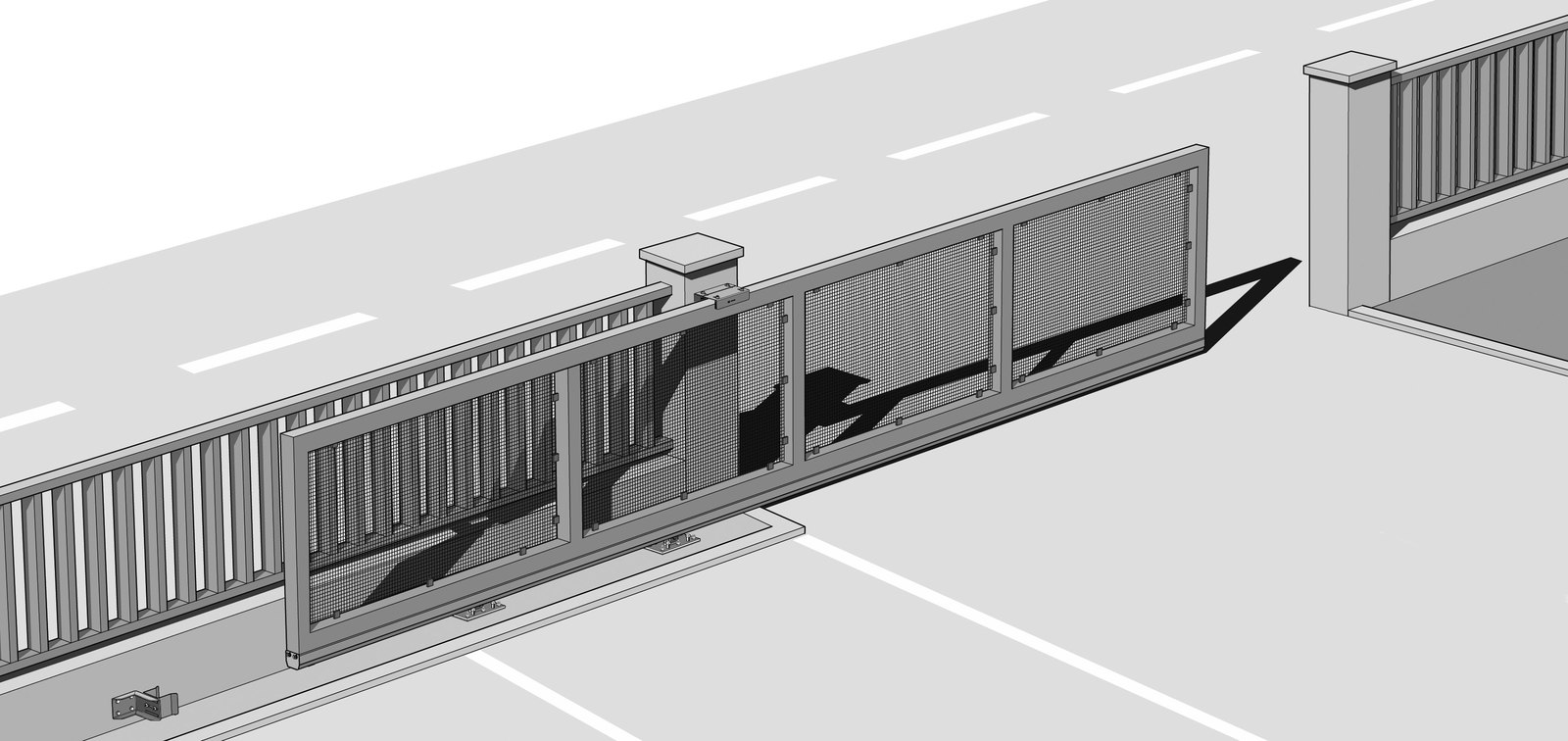
An enclosed roller system helps the DuraGates cantilever slide gate comply with ASTM F2200 & UL325 safety standards. Choosing the right foundation — pad, post, or pier — is the single biggest factor in how long that performance lasts.
Pad Mount — the Recommended Foundation
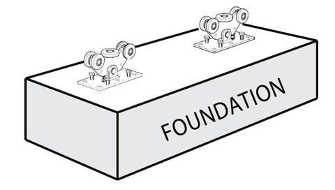
Comunello recommends installing cantilever hardware on a concrete pad. This gives your gate a solid foundation that will help it last for years. Using a single concrete pad helps in two ways:
- Puts both carriages on a single foundation where they will not misalign over time.
- Allows for shorter tail sections by providing the counterbalance weight needed for a stable gate.
The reason most gates get harder to open year after year is wheel misalignment. When the support wheels are mounted on posts, they begin to mis-align as the posts move. Whether it’s because of sandy soil, freeze/thaw cycles, or just the weight of a cantilever gate hanging off them, gate posts move over time — and that movement creates friction that makes the gate harder to open.
Not all installations allow for the use of a concrete pad, and not all installers want to pour one. You have two other options for installing DuraGates:
Foundation Option 1
Pad Mount
A single poured concrete pad carries both carriages and doubles as the gate’s counterbalance weight. Recommended for every installation.
View pad mount guide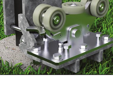
Foundation Option 2
Post Mount
Carriages bolt to brackets on 4″ posts set in concrete. Limited to Mini/Piccolo hardware under 1,200 lbs.
View post mount guide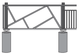
Foundation Option 3
Pier Mount
Two separate concrete piers support the carriages directly — a good option when a continuous pad isn’t practical.
View pier mount guideConcrete Pad
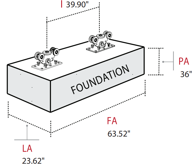
The concrete pad dimensions given in the configurator are based on the total gate length (LT) and weight (P) determined by the configuration. The concrete pad acts as the counterbalance weight for the gate, allowing for shorter tail sections than traditional hardware. Two important factors to consider about the pad are:
- The pad dimensions given are long enough to support the carriages and heavy enough to act as the counterbalance, but do not take the frost line into consideration.
- The pad MUST be dug below the frost line to prevent heaving caused by the freeze/thaw cycle.
The pad dimensions determine the volume of concrete necessary to provide a counterweight. If you alter the length, width, or depth of the pad, make sure you do not reduce the total volume:
Concrete Volume Formula
YARDS = (LA × P × FA) / 46,656
Worked Example
For a foundation 63″ long × 24″ wide × 36″ deep, it would need 1.2 yards of concrete:
Yards = (63 × 24 × 36) / 46,656 = 1.2 yards
The carriages may be post mounted or pier mounted instead of pad mounted, and if done properly, it will not significantly impact the performance of the gate — although it will likely shorten the service life of the gate and hardware due to mis-alignment issues over time.
Post Mount Installation Suggestions
Post mount installations should only be done on gates using “Mini” or “Piccolo” hardware and have a weight over the opening of less than 1,200 lbs.
The recommended installation method is to mount the post brackets to fall-over posts installed on the opposite side of the gate from the fence line. Mount the post brackets as close to the ground as possible — the bottom of the bracket plate should be within 2″ of ground level. When possible, it is best to let the bottom plate rest on the concrete pier holding the post.
The hole diameter and depth are determined by the configured pad size. You need half the amount of concrete poured into each post hole to carry the weight of the gate without failing.
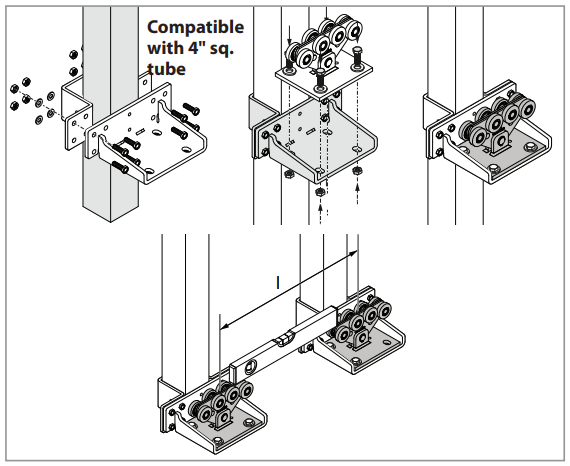
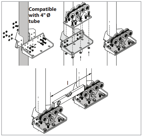
In a typical post mount installation, you will set the posts into 16″ to 26″ diameter holes and mount the carriages to brackets bolted or welded to the posts. Post brackets are available for the Mini and Piccolo systems (steel and aluminum) and are designed to fit either 4″ round or 4″ square posts.
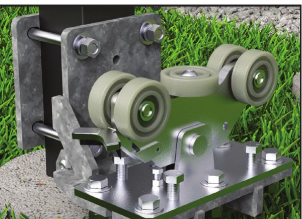
A Real-World Post Mount
Here the carriage bolts straight to a steel bracket welded to the post, with the plate resting on the concrete pier below — exactly the arrangement described above.
Setback from the Opening
- The “front” gate mounting post should be set back 13″ from the edge of the opening to the center of the post.
- The “rear” gate mounting post should be set so the center-to-center distance between the front and rear posts equals the interaxis (I) distance from the configuration.
Setback from the Fence Line
- Post brackets installed on a fall-over post facing the fence (mounted on the opposite side of the gate from the fence line): the setback dimension is measured from the face of the post to the end post or column face.
- Post brackets installed on fence line / end posts (mounted between the gate and the fence): the setback is defined by the bracket width, as follows:
Post Setback for UL325
| Gate Profile | Post Setback |
|---|---|
| 2″ | 6-1/2″ |
| 2-1/2″ | 6-3/4″ |
| 3″ | 6-7/8″ |
| 4″ | 7-3/8″ |
| 6″ | 8-3/8″ |
Gap Between Gate & Fence
| Profile | Gap |
|---|---|
| 2″ | ~2-1/2″ |
| 4″ | ~1-1/2″ |
| 6″ | ~1/2″ |
- Install the “front” carriage on the end post at the opening, which will leave the gate protruding about 12″ into the opening; or set a second post about 13″ back from the end post to allow the gate to open fully behind the fence line.
- Install an “extra” post at the position specified by the configuration to match the carriage spacing (I). It is okay to extend the carriage mounting position back (longer) to the next post if desired, but you must follow the guidelines for “Extending the tail length of the gate.” It is NOT ACCEPTABLE to reduce the carriage spacing to match up with a line post.
Hole Diameter Calculation
Since DuraGates are shorter, we use the concrete as part of the gate’s counterweight. You need to use the amount of concrete shown in a minimum-length configuration to hold the gate in the ground. Calculate the size of the post holes needed to carry half the weight of the foundation using the formula:
Post Hole Volume Formula
Volume (hole) = πr²h
Or use an online calculator like this concrete hole volume calculator.
Worked Example
Continuing the example above, for a foundation 63″ long × 24″ wide × 36″ deep, you would need two holes 26″ diameter and 51″ deep.
- Dig the holes and set the posts in concrete equal to the volume specified by the configuration.
- Dig the hole to a depth below the frost line.
- Connect the two carriage support posts mechanically in two positions, if possible. This keeps the two carriages from moving independently in the direction of the gate and reduces misalignment over time.
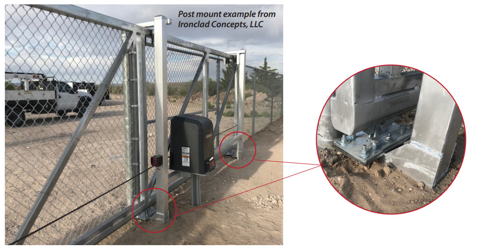
Carriages Mounted on Post Brackets
Here’s an example of carriages mounted on post brackets instead of a pad — the base plate bolts directly to a welded bracket at the bottom of each post.
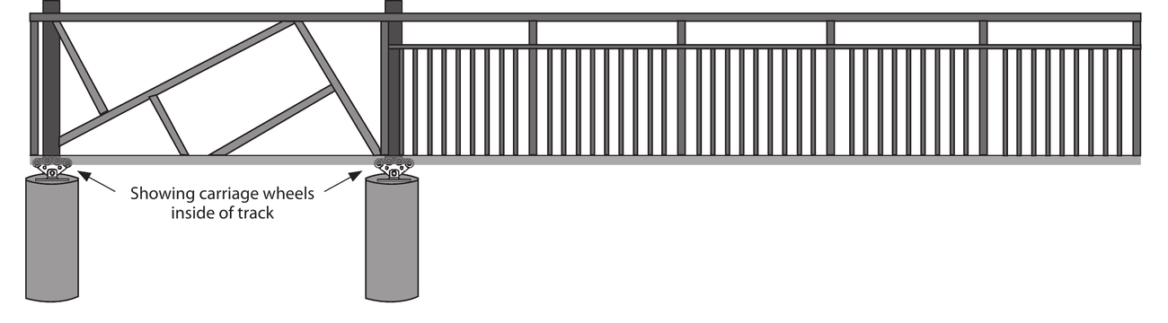
Pier Mount Installation
In a pier mount installation, pour two separate concrete foundations — typically 16″ to 26″ diameter holes dug to a minimum of 48″, or below the frost line if it is deeper. The carriage is mounted directly on the concrete pier, and the rest of the installation is the same as installing on a single concrete foundation. The minimum diameter of the pier is determined by the carriage length, because the anchor bolts need 4″ of concrete from the mounting holes to the edge of the concrete so it doesn’t break out:
| Carriage Size | Standard | Integrator |
|---|---|---|
| Mini “M” Carriages | 16″ min. dia. | 24″ min. dia. |
| Large “P” Carriages | 20″ min. dia. | 24″ min. dia. |
Setback from the Opening
- Place the “front” pier just behind the end post at the opening so the carriage can be installed on the pier with the base plate 6 to 8 inches from the edge of the opening.
- Place the “back” pier at the position specified by the configuration to match the carriage spacing (I), so the center of the two piers is the same as the configuration Interaxis (I).
Setback from the Fence Line
- The setback from the fence line is usually determined by the need to automate the gate and have the final installation meet UL325 Safety code. UL325 specifies a gap of 2-1/4″ or less between the end post or column on the fence and the moving gate. The pier will usually need to be placed where its center is 6 to 8 inches from the fence line to meet this spec.
Pier Diameter Calculation
Since DuraGates are shorter than other types of cantilever gates, we use the concrete as part of the gate’s counterweight. You need to use the amount of concrete shown in a minimum-length configuration to hold the gate in the ground. Calculate the size of the post holes needed to carry half the weight of the foundation using the formula:
Pier Hole Volume Formula
Volume (hole) = πr²h
Or use an online calculator like this concrete hole volume calculator.
Worked Example
Continuing the example above, for a foundation 63″ long × 24″ wide × 36″ deep, you would need two holes 26″ diameter and 51″ deep.
- Dig the holes and set the posts in concrete equal to the volume specified by the configuration.
- Dig the hole to a depth below the frost line.
Always Confirm With Your Configuration
Pad, post, and pier dimensions shown here are examples only. The exact pad size, hole diameter, and depth for your gate are generated by the DuraGates configurator based on your gate’s total length and weight — always dig to the dimensions specified for your specific configuration, and always dig below the local frost line.